|
Industrial Calibration
1.0.0
|
|
Industrial Calibration
1.0.0
|
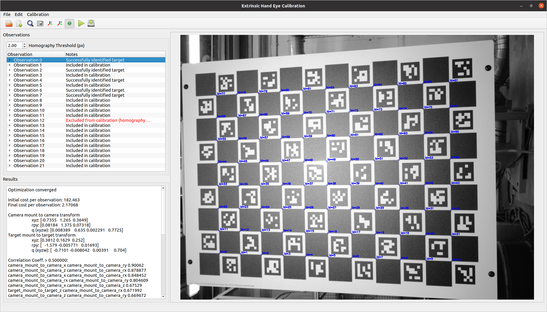
This application performs extrinsic hand-eye calibration based on 2D camera images and measured camera/target poses. The application requires a file that specifies the configuration of the calibration problem and the observation data to be used in the calibration. The outputs of this calibration are:
Run the application by executing the compiled executable from the install directory of the colcon workspace in which it was built:
Alternatively, use ROS2 to start the application:
The observation data for this application consists of:
The observation data and YAML file can be generated by the calibration data collector node in industrial_calibration_ros. Alternatively, users can collect calibration data manually and generate the observation YAML file by hand.
Pose files should be specified as a position vector in meters and quaternion, in the following format:
The observations should be collated into a YAML file (e.g., cal_data.yaml) that lists each corresponding pair of image and pose files. The image and pose files should be specified by their local directory, relative to the location of this file.
Additional configuration information about the system also needs to be provided in order to perform the calibration. The configuration can be generated and saved to YAML file from the GUI using the icons and menu options. The format of the YAML configuration file is as follows:
Camera intrinsic parameters for a pinhole model camera, without distortion
Initial guess for the transform from the camera mount frame to the calibrated camera frame
Initial guess for the transform from the target mount frame to the calibrated target frame
Plugin configuration for target finder used to detect the calibration target in the image observations.
Here is an example configuration for a ModifiedCircleGridTargetFinder:
Here is an example configuration for a CharucoGridBoardTargetFinder:
In general, we want to ensure that the calibration target features observed in an image matches closely to the known geometry of the target. For planar calibration targets and 2D images, we can do this by computing a homography transform between the known target features and the observed target features. This homography transform projects the known target features onto the observed target features, allowing us to measure the average distance between corresponding features (in pixels). If the average homography error is above a specified threshold value, we want to exclude that observation from the calibration because the observed target match close enough to our known target geometry.
Flag indicating whether the camera is static in the calibration
Here is an example of a calibration configuration YAML file:
Residual error is the average squared error between the detected and expected target features remaining at the end of the calibration optimization. In the case of this optimization, the units of the residual error are squared pixels.
Residual error generally scales with the size (in pixels) of each target feature (e.g., a checkerboard intersection) in the image.
For example, in the case of a high resolution camera, a 10x10 neighborhood of pixels might represent a checkboard intersection. In a lower reslution camera, however, the same checkboard intersection might only be represented by a 2x2 neighborhood of pixels. Calibration with the high resolution camera will likely result in a higher residual error because a distance in physical space (e.g., mm) maps to a greater number of pixels in image space.
In addition to evaluating error in image space, it is possible to project that error back into physical 3D space (under the assumption that the calibration target is planar). Like residual error, this measure of error reports the average distance between a detected target feature and its expected location. However, this error metric is generally more meaningful than residual error because it reports average error in physical units (e.g., mm) and is not influenced by the resolution of the calibration images.
This calibration algorithm assumes that the measurement of the pose from the target mount frame to the camera mount frame ( 
To understand the generally effect of this "perfect pose measurement" assumption, we run a PnP optimization for each acquired image and compare its reported camera-to-target transform ( 

If the measurement of
A correlation coefficient is a number on [-1, 1] describing how interrelated two variables are to one another.
In the context of a calibration optimization problem, ideally all calibration variables are independent of one another, and all correlation coefficients should therefore be 0.
In practice, this is generally not true, but all correlation coefficients should be relatively low. A very high correlation coefficient between any two variables (typically > 0.8) generally means that two variables play the same role in reducing the overall optimization cost and cannot be accurately distinguished from one another.
High correlation coefficients in the context of extrinsic hand-eye calibration typically indicate that not enough variety of camera poses were used for the calibration. To correct, add images from camera poses that look at the calibration target from a variety of different angles.