URDF
Introduction
The Unified Robot Description Format (URDF) is an XML-based format used to describe the structure, kinematics, and visual properties of a robot in ROS 2. It provides a standardized way to define robot models, including links, joints, and sensors, making it essential for simulation, visualization, and control of robot.
Before starting the tutorial on URDF, here is the basics to know before we get started.
XML Robot Description Format
The Unified Robot Description Format is an XML specification to describe a robot. We attempt to keep this specification as general as possible, but obviously the specification cannot describe all robots. The main limitation at this point is that only tree structures can be represented, ruling out all parallel robots. Also, the specification assumes the robot consists of rigid links connected by joints; flexible elements are not supported.
The specification covers:
Kinematic and dynamic description of the robot
Visual representation of the robot
Collision model of the robot
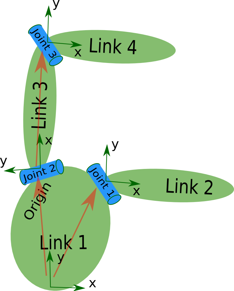
The description of a robot consists of a set of link elements, and a set of joint elements connecting the links together. So a typical robot description looks something like this:
<?xml version="1.0"?>
<?xml-model href="https://raw.githubusercontent.com/ros/urdfdom/master/xsd/urdf.xsd" ?>
  <robot name="pr2" xmlns="http://www.ros.org">
  <link> ... </link>
  <link> ... </link>
  <link> ... </link>
  <joint>  ....  </joint>
  <joint>  ....  </joint>
  <joint>  ....  </joint>
  </robot>
XML Specification
< robot> element
Theroot element in a robot description file must be a robot, with all other elements must be encapsulated within.
Below is an example showing a robot with name my_robot and its elements(joints, links, etc ) which are defined inside the robot element.
<robot name="my_robot">
    <link name="base_link"/>
    <link name="wheel"/>

    <joint name="wheel_joint" type="continuous">
        <parent link="base_link"/>
        <child link="wheel"/>
        <origin xyz="0 0 0.1"/>
        <axis xyz="0 0 1"/>
    </joint>
</robot>
2. Elements of < robot>
Link
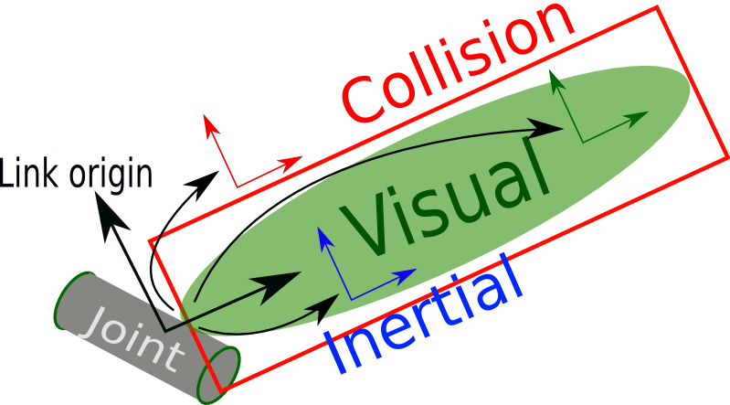
The link element describes a rigid body with an inertia, visual features, and collision properties.
Example:
<link name="my_link">
      <inertial>
        <origin xyz="0 0 0.5" rpy="0 0 0"/>
        <mass value="1"/>
        <inertia ixx="100"  ixy="0"  ixz="0" iyy="100" iyz="0" izz="100" />
      </inertial>

      <visual>
        <origin xyz="0 0 0" rpy="0 0 0" />
       <geometry>
         <box size="1 1 1" />
       </geometry>
       <material name="Cyan">
         <color rgba="0 1.0 1.0 1.0"/>
       </material>
     </visual>

     <collision>
       <origin xyz="0 0 0" rpy="0 0 0"/>
       <geometry>
         <cylinder radius="1" length="0.5"/>
       </geometry>
     </collision>
   </link>
Attribute
Name (required)
Specifies a unique name of the joint
Here name is an attribute and is the name of the link itself.
Elements
< inertial> (optional) – Defines the mass, center of mass, and inertia.
< origin> (optional) – Specifies the center of mass relative to the link frame.
< mass> – Sets the link’s mass.
< inertia> – Defines moments and products of inertia.
< visual> (optional) – Specifies the appearance of the link.
< geometry> (required) – Defines shape (
, , , or ). < material> (optional) – Defines color (
) and texture ( ). < origin> (optional) – Sets position and orientation relative to the link.
< collision> (optional) – Defines the collision model, often simpler than the visual model.
< geometry> – Uses the same shape options as
. < origin> (optional) – Sets position and orientation for collision calculations
For more details of each elements , refer URDF Link.
Joint
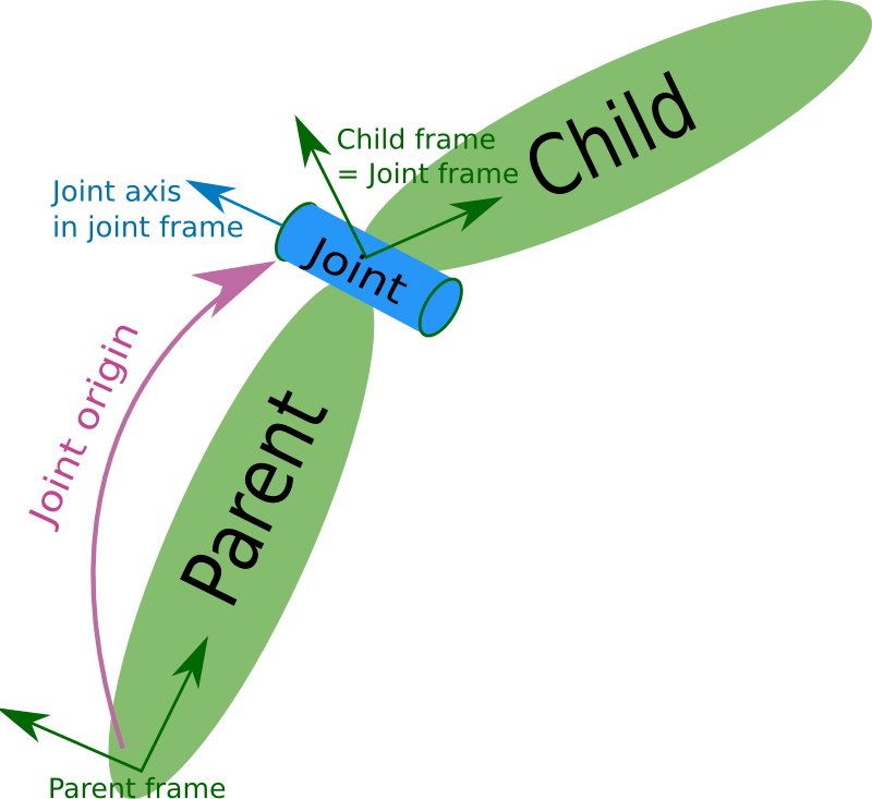
The joint element describes the kinematics and dynamics of the joint and also specifies the safety limits of the joint.
Example:
     <joint name="my_joint" type="floating">
        <origin xyz="0 0 1" rpy="0 0 3.1416"/>
        <parent link="link1"/>
        <child link="link2"/>

        <calibration rising="0.0"/>
        <dynamics damping="0.0" friction="0.0"/>
        <limit effort="30" velocity="1.0" lower="-2.2" upper="0.7" />
        <safety_controller k_velocity="10" k_position="15" soft_lower_limit="-2.0" soft_upper_limit="0.5" />
    </joint>
Attribute
Name (required)
Specifies a unique name of the joint
Here name is an attribute and is the name of the joint itself.
Type (required)
Specifies the type of joint, where type can be one of the following:
revolute — a hinge joint that rotates along the axis and has a limited range specified by the upper and lower limits.
continuous — a continuous hinge joint that rotates around the axis and has no upper and lower limits.
prismatic — a sliding joint that slides along the axis, and has a limited range specified by the upper and lower limits.
fixed — this is not really a joint because it cannot move. All degrees of freedom are locked. This type of joint does not require the
, , , or <safety_controller>. floating — this joint allows motion for all 6 degrees of freedom.
planar — this joint allows motion in a plane perpendicular to the axis.
Elements
< origin> (optional) – Defines the joint’s position (xyz) and rotation (rpy) relative to the parent link.
< parent> (required) – Specifies the parent link in the robot structure.
< child> (required) – Specifies the child link.
< axis> (optional, default: (1,0,0)) – Defines the axis of motion for revolute and prismatic joints.
< calibration> (optional) – Sets reference positions for joint calibration.
< dynamics> (optional) – Defines damping (resistance to motion) and friction.
< limit> (required for revolute & prismatic joints) – Specifies motion constraints: lower and upper limits, effort, and velocity.
< mimic> (optional) – Makes a joint replicate another joint’s movement using a multiplier and offset.
< safety_controller> (optional) – Sets safety limits (soft_lower_limit, soft_upper_limit) and safety parameters (k_position, k_velocity).
< type> (required) – Defines the joint type: revolute, continuous, prismatic, fixed, floating, or planar.
For more details of each elements , read URDF Joint.
What is Xacro?
Xacro (XML Macros) Xacro is an XML macro language. With xacro, you can construct shorter and more readable XML files by using macros that expand to larger XML expressions. This is most useful when working with large XML documents such as robot descriptions. It is heavily used in packages such as the urdf.
Advantages of using xacro are:
Define variables and reuse them
reate macros for repeated robot components
Make your URDF cleaner, shorter, and easier to maintain
Example:
<xacro:macro name="simple_box" params="name length color">
  <link name="${name}">
    <visual>
      <geometry>
        <box size="${length} 0.1 0.1"/>
      </geometry>
      <material name="${color}">
        <color rgba="0 1 0 1"/>
      </material>
    </visual>
  </link>
</xacro:macro>
A macro can be defined as above and can be reused by calling as defined below.
<xacro:simple_box name="link1" length="1.0" color="green"/>